
| Form 434 | PARTS LIST |
| 9/2/2015 | www.wallacecranes.com |
Steel and Aluminum 3-Ton Adjustable Height Gantry Crane 15′ 10″ Overall Height, 9-Foot 10-Inch Clear Span
MODEL NUMBER S6T15-A15AC
Click here to print / download PDF File
*download includes Parts List, Parts Location and Cantilever Chart
| ITEM NO. | PART DESCRIPTION | PART NUMBER | QUAN. |
|---|---|---|---|
| 1 | MAIN LEG BRACKET | 1551-0000 | 4 |
| 2 | SUPPORT PIN 11/16 DIA. X 4 9/16 LG. | 5017-0004 | 4 |
| 3 | SPACER BAR 27 LG. | 1744-0006 | 2 |
| 4 | COTTER PIN 1/4 X 1 1/4 LG. | 60-0070 | 8 |
| 5 | NEX. NUT 3/8-24NC | 54-0100 | 4 |
| 6 | SOC. SET SCREW 3/8-24NF X 1 3/4 LG. | 63-0110 | 4 |
| 7 | SOC. SET SCREW 3/8-24NF X 1 LG. | 63-0100 | 4 |
| 8 | LEG BRACE BRACKET | 1763-0000 | 4 |
| 9 | SUPPORT PIN 11/16 DIA. X 4 1/8 LG. | 2853-0000 | 4 |
| 10 | MAIN LEG SWIVEL PIN | 1559-0000 | 4 |
| 11 | LEG BRACE SWIVEL PIN | 1563-0000 | 4 |
| 12 | HEX. HD. BOLT 3/4-10NC X 2 1/2 LG. | 51-0480 | 4 |
| 13 | TROLLEY STOP ANGLE | 5132-0000 | 4 |
| 14 | KEY RING 2 1/4 OD. | 82-0030 | 10 |
| 15 | CAUTION TAG No. 399 | 1969-RING | 12 |
| 16 | LOCK WASHER INT. TOOTH 3/4 | 58-0040 | 4 |
| 17 | HEX. NUT 3/4-10NC | 54-0040 | 4 |
| 18 | I BEAM AL. 12″ X 15′ LG. REINF. | 1680-0151 | 1 |
| 19 | LEG BRACE ASSEMBLY | 1543-0100 | 4 |
| 20 | MAIN LEG ASSEMBLY | 1665-0101 | 4 |
| 21 | UPPER MAIN LEG | 1666-0100 | 4 |
| 22 | ROLL PIN 5/32 X 3/4 LG. | 61-0300 | 4 |
| 23 | LOAD PIN | 3016-0000 | 4 |
| 24 | EXTENSION SPRING | 1017-0000 | 8 |
| 25 | LOWER MAIN LEG | 1672-0100 | 4 |
| 26 | CASTER FRAME ASSEMBLY | 699-0030 | 2 |
| 27 | LOWER MAIN LEG PIN ASSEMBLY | 1999-0000 | 4 |
| 28 | HEX. HD. BOLT 1/2-13NC X 5 1/2 LG. | 51-0470 | 4 |
| 29 | SAFETY CABLE ASS’Y 121″ LG. | 1967-0020 | 2 |
| 30 | OUTER CASTER FRAME TUBE | 700-0030 | 2 |
| 31 | CASTER FRAME ADJUSTMENT PIN | 1392-0000 | 2 |
| 32 | INNER CASTER FRAME TUBE | 701-0030 | 2 |
| 33 | CASTER CASTING FOR INNER TUBE | 2630-0000 | 2 |
| 34 | CASTER CASTING FOR OUTER TUBE | 2629-0000 | 2 |
| 35 | LOCK WASHER INT. TOOTH 1/2 | 58-0020 | 4 |
| 36 | HEX. NUT 1/2-13NC | 54-0050 | 4 |
| 37 | HEX. HD. BOLT 1/2-13NC X 1-1/2″ LG. | 51-0290 | 16 |
| 38 | LOCK WASHER INT. TOOTH 1/2 | 58-0020 | 16 |
| 39 | HEX. NUT 1/2-13NC | 54-0050 | 16 |
| 40 | CASTER WHEEL 8″ DIA. | 47-81NB | 4 |
| 41 | SAFETY STOP ASSEMBLY | 3112-0001 | 4 |
| 71 N. Bacton Hill Rd | wallace@wallacecranes.com | 800-553-5438 |
| Malvern PA 19355-1005 | 610-647-1400 |
I-Beam Assembly Parts Location Diagram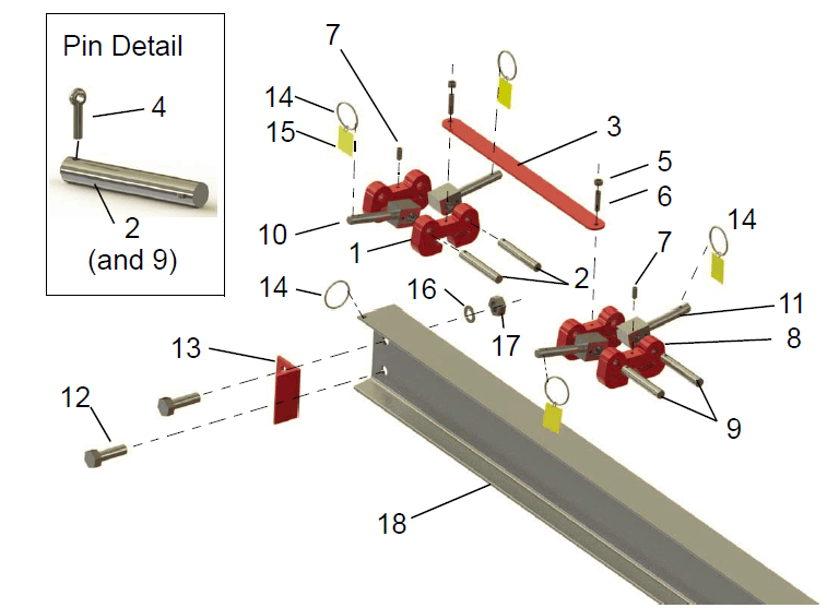
Caster Frame Assembly Parts Location Diagram
| Form 123 | |
| 1/8/2013 |
Wallace Cranes
Portable Crane Cantilever Chart
| Gantry Model Number: | S6T15-A15AC |
| I-Beam: | A12″ x 11.0#/’ x 15′ |
| I-Beam Length (Overall Span): | 180 Inches |
| Maximum Cantilever Distance (A): | 45 Inches |
| Gantry Rated Capacity: | 6000 lbs. |
| Maximum Cantilevered Load (B): | 3600 lbs. |
| Gantry Weight: | 1022.34 lbs. |
| I-Beam Weight: | 198.34 lbs. |

Proper Cantilever Procedures
Required counterweight should not be supported by gantry caster frame.
Load and trolley should be able to freely traverse the I-beam through the main legs and brace legs of the gantry.
| Required Counterweight at (C) | |||||||||
| A | B | B | B | B | B | B | B | B | B |
|---|---|---|---|---|---|---|---|---|---|
| IN
FEET |
400 lbs. |
800 lbs. |
1200
lbs. |
1600
lbs. |
2000
lbs. |
2400
lbs. |
2800
lbs. |
3200
lbs. |
3600
lbs. |
| 1 | 0 | 0 | 0 | 0 | 0 | 0 | 0 | 0 | 10 |
| 2 | 0 | 0 | 0 | 0 | 119 | 242 | 365 | 488 | 611 |
| 3 | 0 | 0 | 113 | 313 | 513 | 713 | 913 | 1113 | 1313 |
| 3.75 | 0 | 55 | 321 | 588 | 855 | 1121 | 1388 | 1655 | 1921 |
Contact us if you need assistance. We have experts on hand to answer all your questions.